|
This is a basic design with a single LM3875TF chip per side, and one shared toroidal transformer. I will be making
two of these amplifiers simultaneously but with a few critical component differences. One
is based on standard components, and one on premium components.
The first thing I did was measure all the component values, specifically to pick out
and pair match components for the standard design as I had two sets. I only had one set of
premium components, but they are inherently more consistent and accurate in measurement anyway.
The following shows the components received from Brian (the PCB designer and distributor) and their measured values.
Standard Component Amplifier:
| Left |
R1 |
220 Ohms |
221.10 Ohms |
| Right |
R1 |
220 Ohms |
221.30 Ohms |
| Left |
R2 |
22k Ohms |
22.11k Ohms |
| Right |
R2 |
22k Ohms |
22.10k Ohms |
| Left |
R3 |
680 Ohms |
671.30 Ohms |
| Right |
R3 |
680 Ohms |
671.70 Ohms |
| Left |
Rnfb |
22k Ohms |
22.30k Ohms |
| Right |
Rnfb |
22k Ohms |
22.30k Ohms |
| Left |
Cs |
1500uf |
- |
| Right |
Cs |
1500uf |
- |
The gain for this amplifier (RNFB/R3) is approximately 33.
Premium Component Amplifier:
| Left |
R1 |
220 Ohms |
219.40 Ohms |
| Right |
R1 |
220 Ohms |
219.40 Ohms |
| Left |
R2 |
22k Ohms |
21.92k Ohms |
| Right |
R2 |
22k Ohms |
21.91k Ohms |
| Left |
R3 |
680 Ohms |
676.70 Ohms |
| Right |
R3 |
680 Ohms |
674.40 Ohms |
| Left |
Rnfb |
22k Ohms |
21.92k Ohms |
| Right |
Rnfb |
22k Ohms |
21.90k Ohms |
| Left |
Cs |
1000uf |
- |
| Right |
Cs |
1000uf |
- |
The gain for this amplifier (RNFB/R3) is approximately 32.
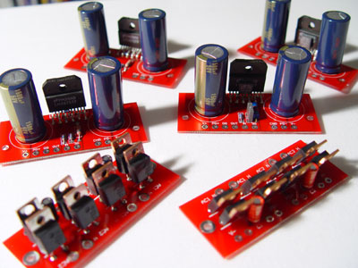
LM3875 amplifier and rectifier PCB boards from Brian Bell.
|