|
Brian's PCB's allowed me to make light
work of building amplifier and rectifier boards, and so I decided to direct my remaining pent up DIY energy into
building a chassis from scratch rather than using a premade chassis.
The first stage was to mock up a design in a CAD package. I found this especially useful as I was about to embark on
my first metalworking experience and wanted to minimise potential mistakes.
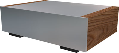
The chassis would be made out of aluminium mostly, completed with wood side panels for more pleasing aesthetics.
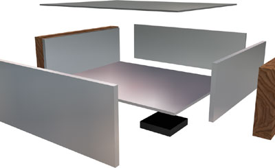
The exploded view shows all the chassis panels. The design has been carefully thought out so that all panels bolt
together securely without requiring any brackets. More importantly my intention was to cover as many side edges as possible so as
to achieve a good end finish. The chassis is similar to that of Peter Daniels Integrated
offering from which I have taken much subconscience influence it seems.
chassis Dimensions:
| Front Panel |
Aluminium |
6 x 300 x 80mm |
| Rear Panel |
Aluminium |
4 x 260 x 80mm |
| Inner Side Panels |
Aluminium |
6 x 200 x 74mm |
| Bottom Panel |
Aluminium |
4 x 200 x 260mm |
| Bottom Panel |
Aluminium |
2 x 200 x 260mm |
| Outer Side Panels |
Beech |
20 x 200 x 80mm |
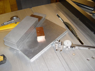
I ordered the metal from a metal supermarket but wasn't to happy with the cuts. They weren't
cut square to begin with and all the panels had been sheared not sawn so the edges required some working too. Using a suitable
non-ferous cutting blade it was possible to recut all the panels on the table saw with suprising ease.
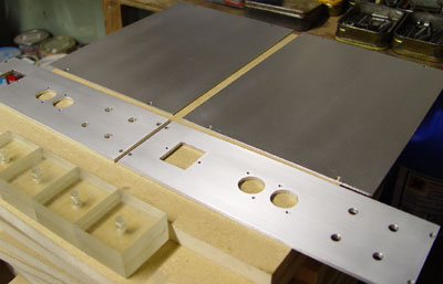
Accurate square cuts using a table saw. The copper panels are heatsinks which will be attached between the chips and
the chassis base.
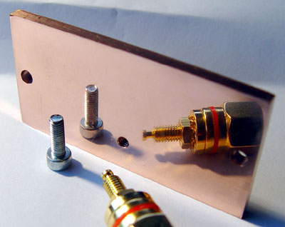
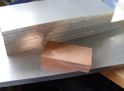
The cut marks remaining on the edges of the panels were removed on the belt sander. The copper heatsinks were finished on the
disc sander going through several grades and finishing on 1200 grit using lots of lubricant to get a good shine and
keep the copper cool.
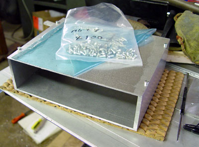
I started putting the chassis together by drilling and tapping M4 holes into the 6mm side panels into which all the other panels would
be attached.
The fully connected bare chassis. Some of the overhung edges were trimmed down using a router and flush trim bit.
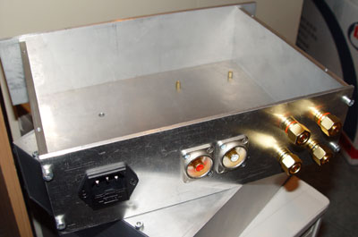
Next I cut the holes for the rear panel. The power connector holes were cut using a scroll saw, and the large holes
for the Neutrik RCA connectors with a 22mm drill bit.
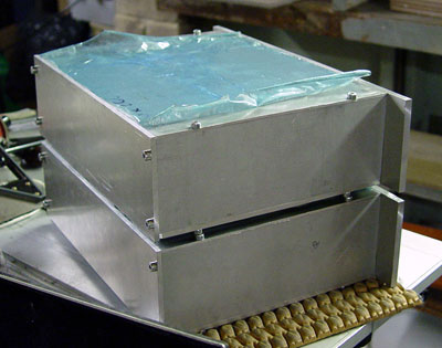
Another shot of the rear and top panels without any fittings. All external panels have been wet sanded by hand using soapy
water, going through 180, 240, 320, and 500 grits, and then spray lacquered to provide a degree of protection. Acrylic
square blocks have been cut and drilled to be used as the chassis feet.
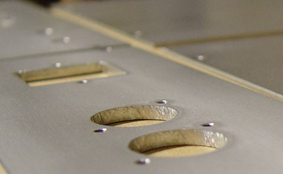
Close up of the lacquered finish.
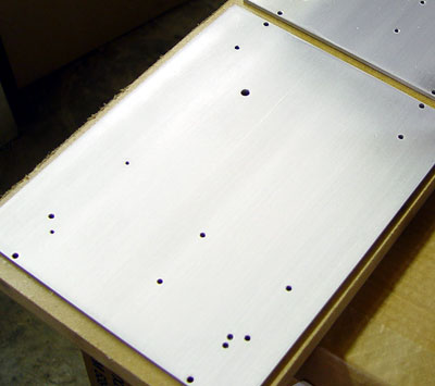
The chassis base with all the fixing holes drilled and tapped. The base will be used as the heatsink via the copper panels.
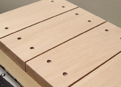
Beech side panels drilled, finely sanded then finished with several coats of Refined Danish Oil.
I eventually decided that a lacquered finish on the aluminium would have insufficient protection and opted to have the
panels anodised instead. This was much more inexpensive than I had originally thought. The panels were sanded down to 320 grit
before being anodised, and the resulting finish was superior and a pleasure to work with (no more accidental scratches).
|