|
The best way to learn something alien (for me it's building an amplifier) is to
jump in head first (using common sense and taking neccessary precautions when working with electricity of course!)
Being a first amplifier project I decided to make it
as cheap as possible, which meant stripping parts from the mounds of old electrical equipment
lying around.
The Transformer
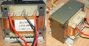
A El core transfromer was salvaged from an old Pioneer SA-540 amplifier that was collecting dust in the attic.
There are two options in connecting this transformer, which will either give 27.5v - 0v - 27.5v, or 30v - 0v - 30v on the
rails. I opted for the 27.5v - 0v - 27.5v to get the lowest voltage after rectification, and even then it is still at
the ceiling of what the LM3875 will take.
Case, Switch, and Power Connector
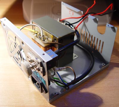
An old PC AT power supply was gutted for the amp housing and I also used the AT power switch that was part of the original PC.
Rectifier Bridge
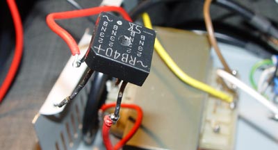
A rectifier bridge was pulled from the same amp as the transformer and soldered to the two 27.5v rails. The measured DC current
output from the bridge measured: +/- 24.9v DC
Smoothing Capacitors
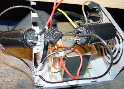
Two 5600uF 42v capacitors were about the best I could find, again pulled from the same amplifier as the trafo and rectifier bridge. In this case I
was concerned more with finding caps with enough voltage rating than with the value of the caps themselves (as long as they were reasonable). After soldering
them to the outputs of the rectifier bridge (watching the polarity carefully) I measured the now smoothed DC: +/- 37.5v DC
LED's
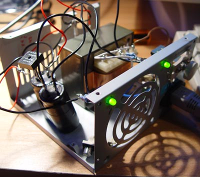
I added two LED's with the hope of reducing the voltage on the rails a bit more. Two paralleled 2.7k resistors were used in series with each LED which I calculated would
operate them near their max voltage rating. The DC
measured: +/- 36.33v DC
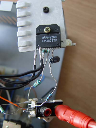
The Amplifier - LM3875TF
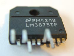
The NC (not connected) pins are cut off the chip. This TF version is the insulated version with stepped pins and should be the easiest type to work with.
I used the schematic provided on National Semiconductor information sheet which is a standard (Non-Inverted) topology.
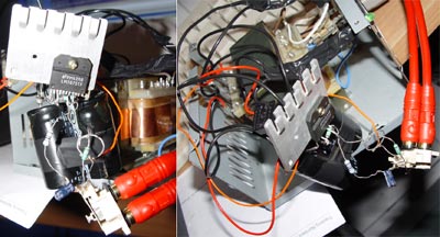
The first working amp has all the components hanging out to make it easier to change and adjust things until I'm happy with it. I used resistors from
my relatively small collection, so the values aren't exactly based on any particular schematic. Some more caps were pulled from the old Pioneer amplifier, and
everything is soldered together P2P.
Following the advice on Nuuk's gainclone FAQ, I measured the DC offset using an 8 Ohm resistor before connecting
any speakers. The measured offset was ~3.5mV which is suprisingly much lower than I was expecting.
Conclusion
The first thing you notice when connecting speakers is how much power it has. Quite impressive. The trafo pushes the chip to its limits and the heatsink gets very hot. This
will be replaced soon with an old CPU heatsink.
Comparing it to a couple of mid-fi cheapo amplifiers lying around, this is clearly better sounding. This is saying a lot considering
that ALL resistors and caps are very old and cheap.
For minimal outlay, this has given massive output, and I can only wonder what my next more seriously designed version will sound like. And so it begins...
|