|
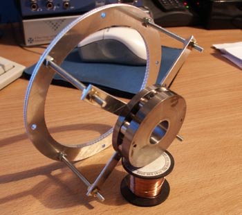
Two months have passed now and things have been slow. In that time the first thing I did was get some
wire. The 0.265mm wire was too thick resulting in ridiculously low impedance, not to mention it scraping
the the top plate in the air gap. So I got some 0.150mm (38 SWG) and 0.125mm (40 SWG) wire. Most of the
voice coils wound in this period have all been usiing the 0.150mm wire. Winding has become a big problem
and machines to do the job are very expensive, so I'll be looking at making a jig to do the winding soon.
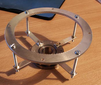
The most notable finding in this time has been that of the suspension. The major drawback in the majority
of conventional dynamic driver designs is that of the spider, as it is in essence acting as a second diaphragm.
The spider however is good as what it does - returns the diaphragm to zero position as quick as possible, stores
as little energy as possible, and provides lateral positioning of the voice coil (centre the voice coil in the air gap).
Its importance is now obvious. However, there are alternatives which some crazed DIY folk have found that may overcome
the spider's drawbacks.
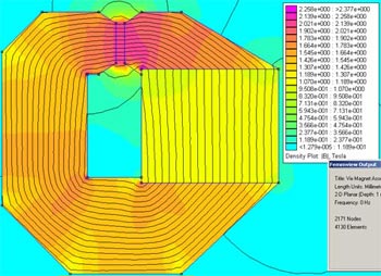
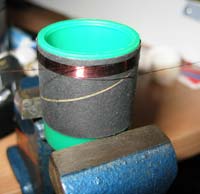
The one I'm most interested is electromagnetic suspension. The idea is conceptually simple, and potentially
has some great advantages. Basically this involves winding two addional coils on the former. These are above and
below the voice coil and supplied with opposing DC current. In doing so, a magnetic force now keeps the former
in the centre of the air gap. By altering the DC voltage we can select a target compliance.
The extra coils mean that an underhung topology would be better to keep all the coils closer in the magnetic field.
This could be seen as a limitation, but since an underhung topology is supposedly better within excursion
limits, I'm not complaining.
This only solves one of the two major jobs taken on by the spider. The second job of laterally positioning
the former is still something that requires a fix. A bit of research has led me to believe that ferrofluid
might be up to the task.
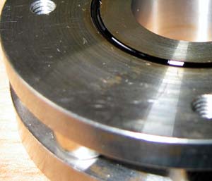
Ferrofluid is an ineresting substance. It provides many welcomed properties in addition to what I want it for, such
as transferring heat away from the voice coil and providing additional damping.
After a couple of messy attempts, I realised that the best way to apply it is before the voice coil is inserted into the
air gap, and with a syringe of some sort. I got some dirty looks when asking for a syringe at the chemist.
I don't think she believed me when I said it was for applying fluid to a speaker.
|